
Msd Atomic Efi Wiring Diagram Free Wiring Diagram
Do you need a comprehensive guide to wire your MSD ignition system? Download the MSD Wiring Manual from MPS Racing and find the detailed diagrams and instructions for various models and applications. You can also check page 31 for the 2-Step Module selector wiring.

Msd 6a 6200 Wiring Diagram
DIGITAL OPERATION The Digital 6A and 6AL use a high speed RISC microcontroller to control the ignition's output while constantly analyzing the various inputs such as supply voltage, trigger signals and rpm.
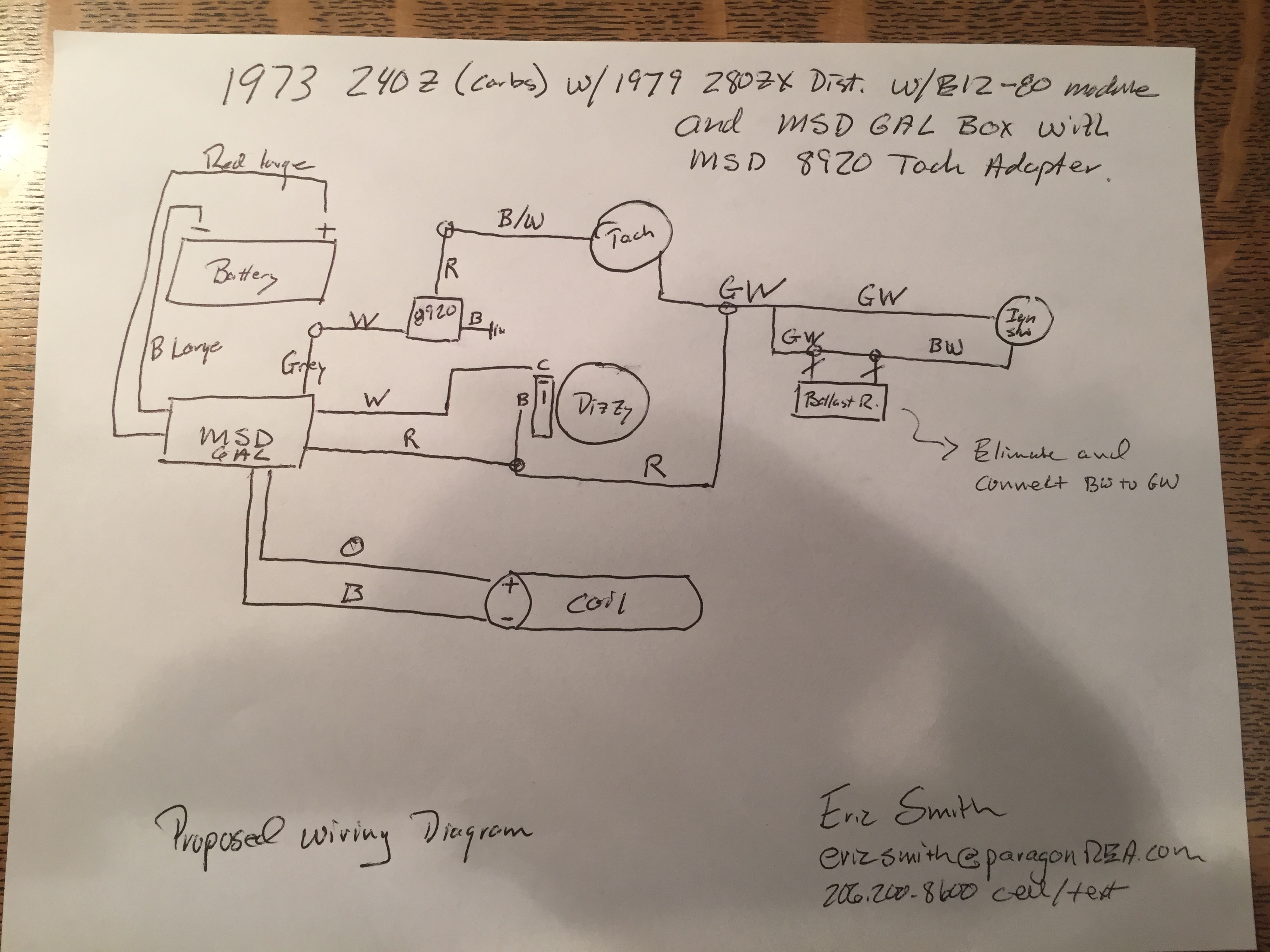
Help...280zx e1280 and MSD 6AL to a 240Z Electrical The Classic
View and Download MSD 6A 6201 installation instructions manual online. Amp Ignition Control Box. 6A 6201 control unit pdf manual download. Also for: 6a 62013, 6al 6425, 6al 64253.
Msd Pn 6425 Wiring Diagram My Wiring DIagram
Support / Ignition Technical Resources Ignition Basics MSD Coil Packs Provide Improved Ignition Capability For Late-Model Engines MSD's LS Series Ignition Controller Means LS Swaps and a Carburetor Too MSD Ignition's Solid State Relays Simplify Your Wiring Layout Upgrade Your MSD Atomic 2 EFI System With These Great Add-Ons
Msd 2 Step Wiring Diagram Cadician's Blog
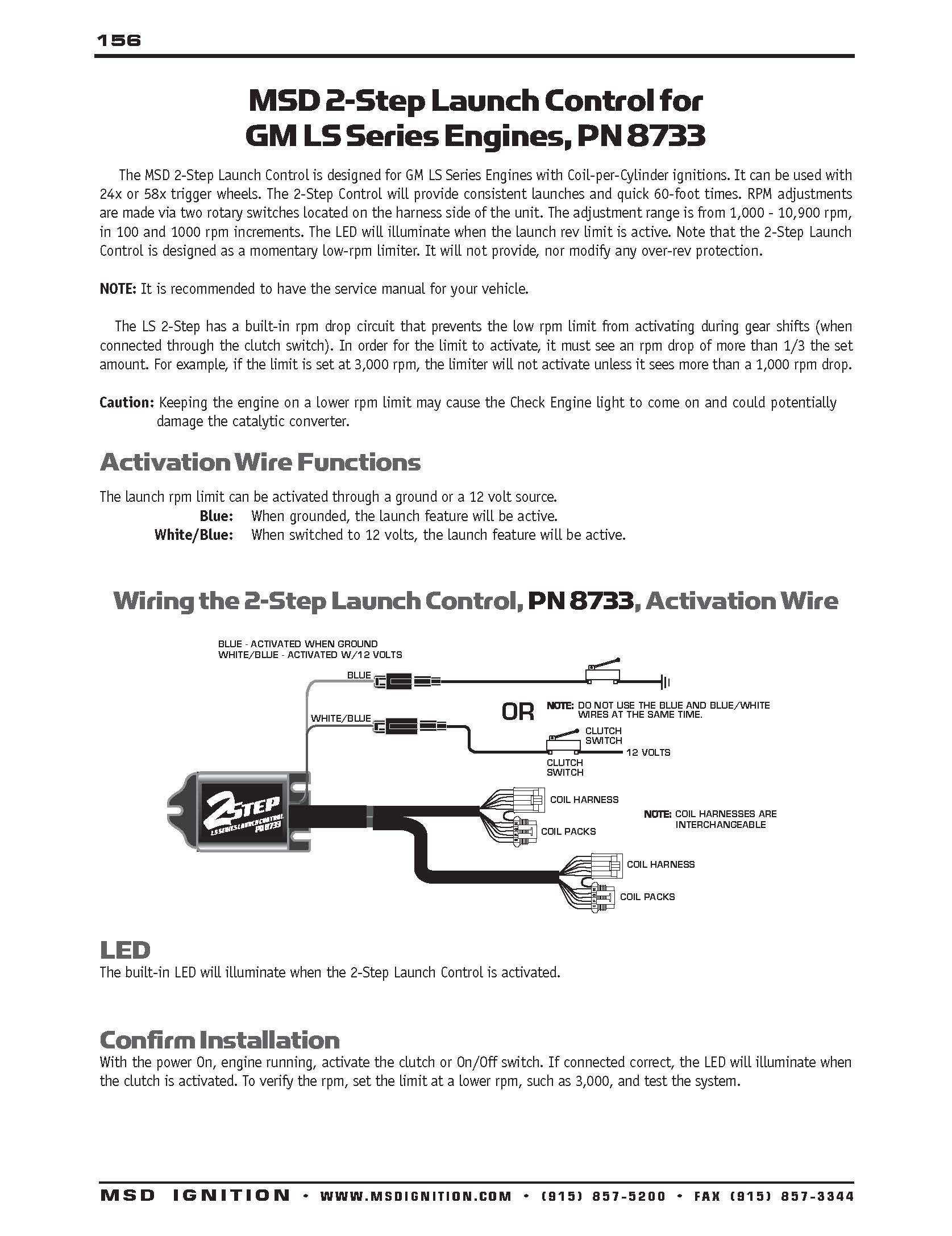
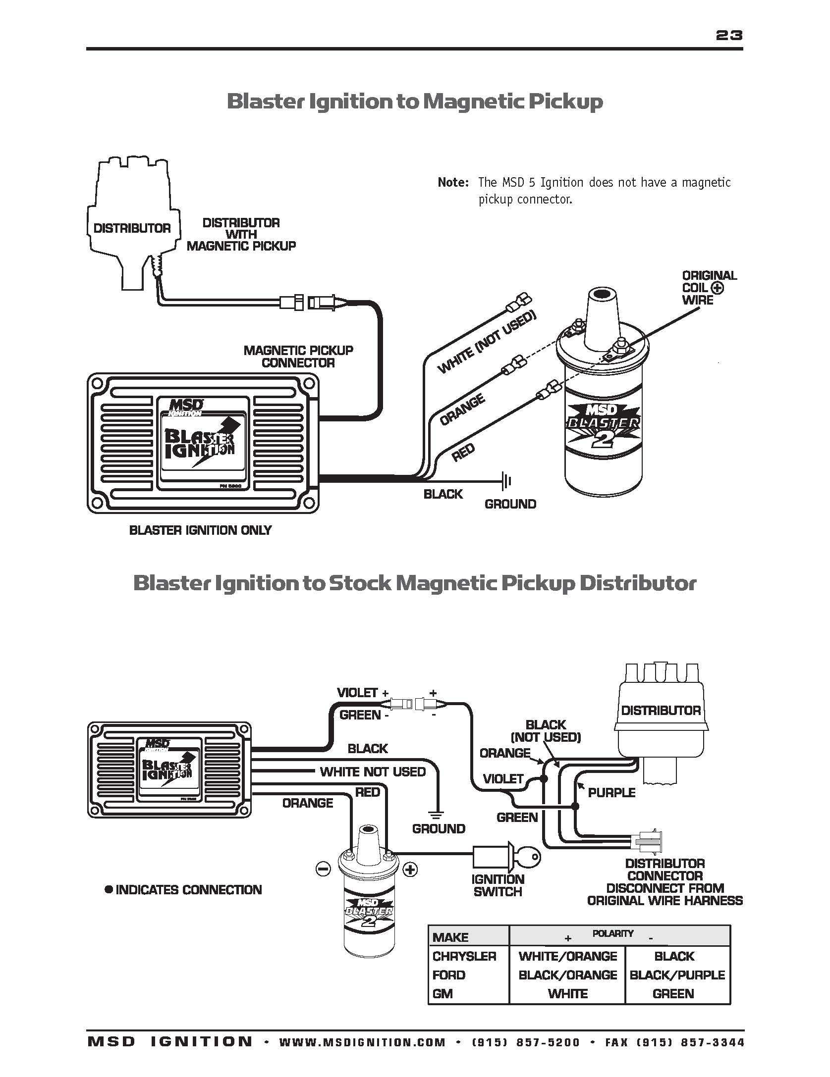
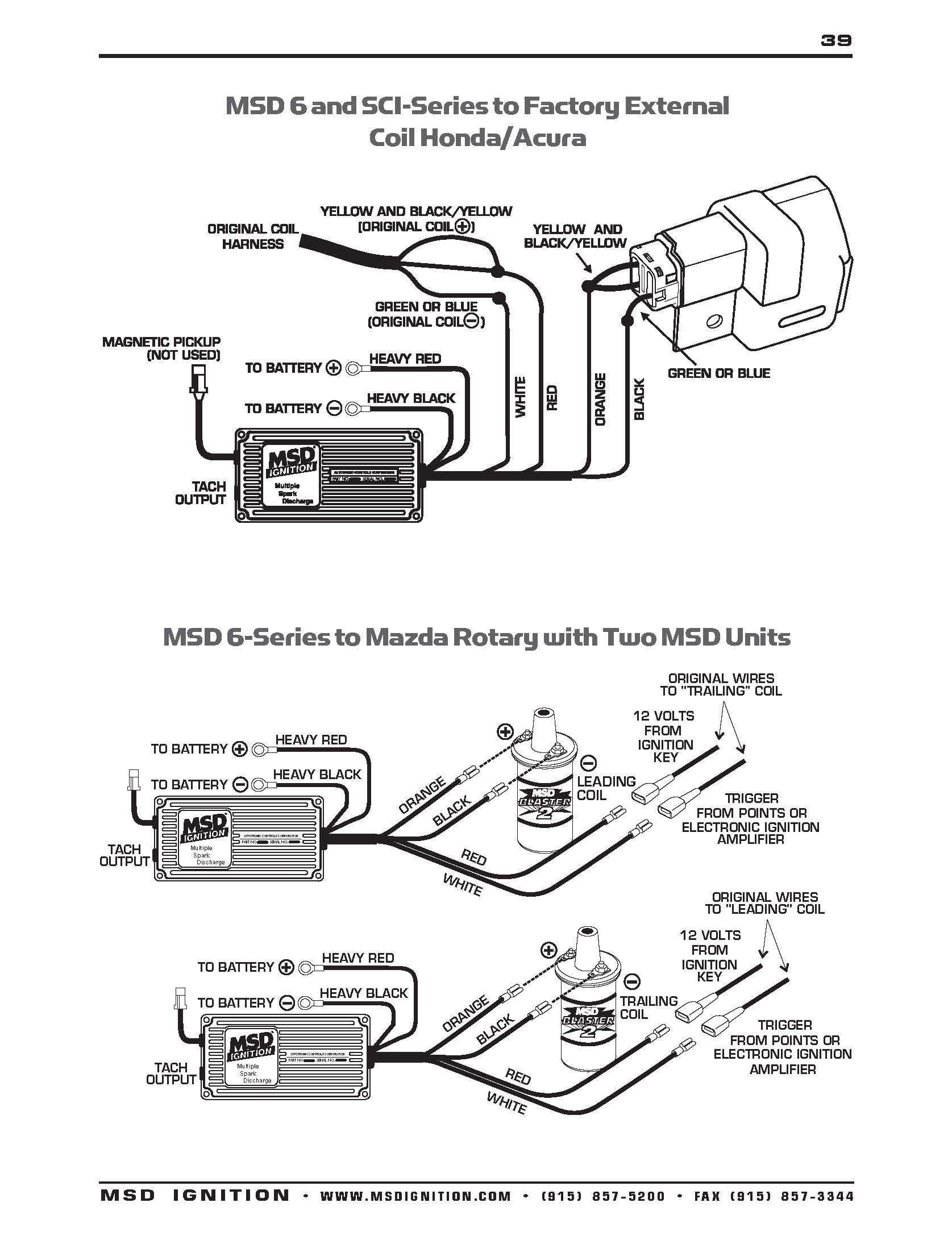
MSD IGNITION • www.msdignition.com • (915) 857-5200 • FAX (915) 857-3344. Accessories Dark Blue. This wire activates the Launch Rev Limit and is the main reset wire for several features of the Ignition. When 12 volts are applied to this wire it will activate the Launch Rev Limit. It also
Msd 7al 2 Wiring Diagram Free Wiring Diagram
INSTALLATION INSTRUCTIONS MSD IGNITION • www.msdignition.com • (915) 857-5200 • FAX (915) 857-3344 MIScELLANEOuS INFORMATION Welding: If you are welding on your boat, to avoid the chance of damage, always disconnect both Heavy Power cables of the MSD (You should also disconnect the tach ground wire too).

Msd 6al 2 Wiring Diagram Free Wiring Diagram
$12.99 Ships Tomorrow Lowest Price Guarantee Add To Cart CD-ROM (Adobe Acrobat PDF) covers all current MSD components, showing how to install them in various ignition systems & engines. Tech info, specs, wiring tips, coil applications, and troubleshooting featured.

Msd Digital 6al Wiring Diagram Free Wiring Diagram
Once the unit is mounted, it's time to focus on the wiring. An MSD must be connected directly to the positive battery terminal to ensure that its transformer and capacitor receive a direct 12 volt power supply. This is the heavy gauge red wire paired with a matching size (10-gauge) ground wire. Ideally, the ground wire would also be connected.

MSD Ignition, Wiring Diagrams and Tech Notes Book Competition Products
BATTERY The MSD Programmable 6AL-2 Ignition Control will operate on any negative ground, 12 volt electrical system with a distributor. The MSD can be used with 16 volt batteries and can withstand a momentary 24 volts in case of jump starts.
Msd Digital 6Al Wiring Diagram Cadician's Blog
DIGITAL OPERATION The Digital 6A and 6AL use a high speed RISC microcontroller to control the ignition's output while constantly analyzing the various inputs such as supply voltage, trigger signals and rpm.
Msd 6A Wiring Diagram Wiring Diagram
The MSD 6014 LS Ignition controller works with 24x/1x, 58x/4x and 58x/1x crank/cam configura-. tions. It auto detects the correct configuration based on the reluctor wheel pattern, so there is no. need to select one. It provides six pre-programmed (non-editable) timing tables for stock engines, three customizable 3-D tables and one customizable.

Msd 6tn Wiring Diagram
The following diagrams show how to wire the crank trigger to MSD Ignition systems. SETTING UP THE DISTRIBUTOR If your distributor is equipped with a centrifugal advance assembly, it must be locked out by welding or bolting the advance mechanism. The distributor has nothing to do with the engine ignition timing when using a crank trigger system.

Msd 6425 Wiring Diagram Free Wiring Diagram
the corresponding diagram. GM used 4, 5 and 7-pin modules in these distributors. NOTE: Some 5-pin models may experience a hesitation or stall on deceleration. If this occurs, contact MSD Tech Line for the required bolt-in diode to correct the problem. MSD Tech Line (915) 855-7123.

Msd 3 Step Wiring Diagram Database
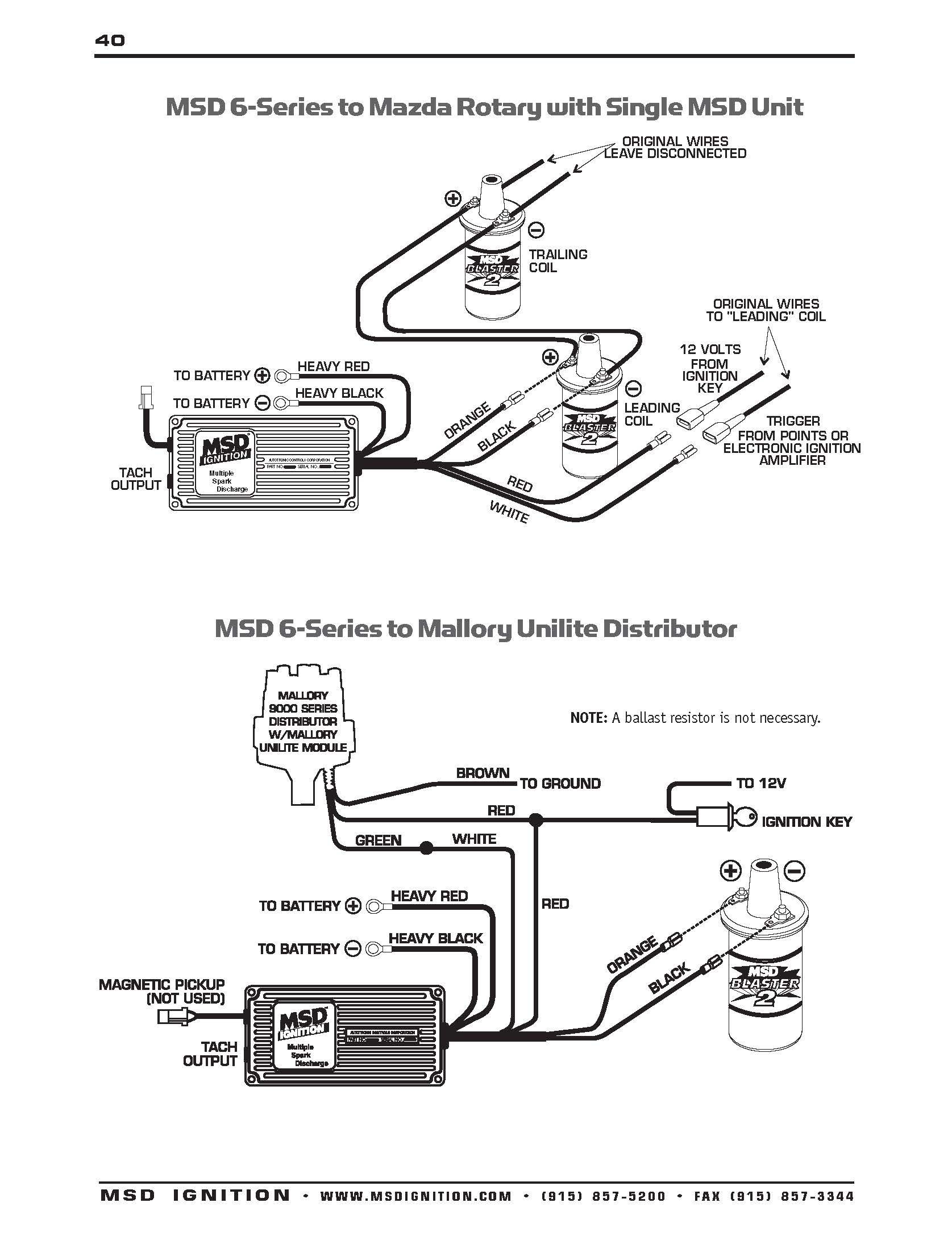
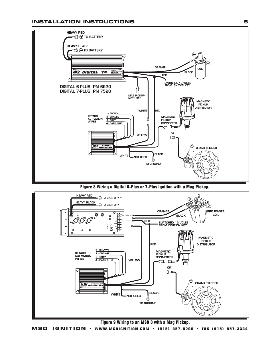
Figure 6 Wiring an MSD 7 Series Ignition with Points/Amplifier. INSTALLATION INSTRUCTIONS MSD IGNITION • www.msdignition.com • (915) 857-5200 • FAX (915) 857-3344 Figure 8 Wiring a Digital 6-Plus or 7-Plus Ignition with a Mag Pickup. Figure 9 Wiring to an MSD 8 with a Mag Pickup..

[How To] Download +28 Msd 7Al 3 Wiring Diagram 2022 Thaimetera Altera
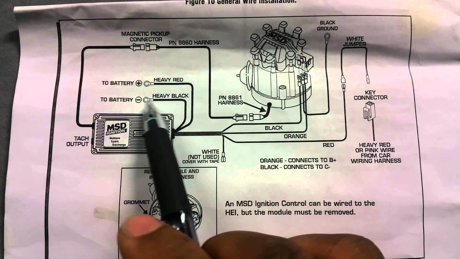
Parts Included: - MSD 6 Series Ignition - Harness, PN 8860 - Harness, PN 8861 - 18" Ground Wire - White Jumper - Red Jumper - Violet Jumpers 4 - 45° Faston Terminals 4 - #8 x 3/4" Screws 2 - 10-32 x 1/2" Screws 4 - 10-32 Hex Nuts 6 - #10 Lock Washers 1 - 100V/1A Diode 4 - Wire Splicers 2 - Wire Ties - Faston Receptacle - Faston Straight Terminals
Hei Wiring Diagram Wiring Library Hei Wiring Diagram Cadician's Blog
MSD Digital 6AL Highlights - PN 6425. • Integrated rotary dials eliminates the need for pills. • Same mounting foot print as the previous 6AL. • Weather-proof connector utilizes some wire color coding has previous generations. • Must use new digital two step box - not compatible with older pill-style versions.
